1. Уводзіны і большview
The SparkFun Pro Mini ATmega328-3.3V/8MHz is a compact microcontroller development board designed for projects where space is a premium. It is compatible with Arduino boards and the Arduino IDE, offering a powerful ATmega328 microcontroller in a small form factor. This board operates at 3.3V and 8MHz, making it suitable for low-power applications and direct interfacing with 3.3V peripherals without additional level shifting.
This manual provides essential information for setting up, operating, and maintaining your SparkFun Pro Mini.

Малюнак 1: Верх view of the SparkFun Pro Mini ATmega328-3.3V/8MHz Development Board.
2. Асноўныя магчымасці
- Мікракантролер: ATmega328 running at 8MHz with an external resonator (0.5% tolerance).
- Аперацыйная Voltage: 3.3В.
- Спажываная магутнасць: RAW pin supports 3.4V to 12V DC input; VCC pin requires regulated 3.3V.
- Рэгулятар: On-board 3.3V regulator with a maximum 150mA output, over-current protected.
- Падключэнне: Designed for direct connection to an FTDI Basic Breakout board (sold separately) for programming.
- Аналагавыя кантакты: 8 analog input pins (A0-A7), with A4, A5, A6, A7 located off-edge.
- Лічбавыя шпількі: Standard GPIO pins, including PWM capabilities.
- Паказчыкі: On-board Power and Status LEDs.
- Памеры: Approximately 0.7 x 1.3 inches (18 x 33mm).
- I2C: Footprints for optional I2C pull-up resistors.

Figure 2: The SparkFun Pro Mini shown with a ruler, illustrating its compact dimensions.
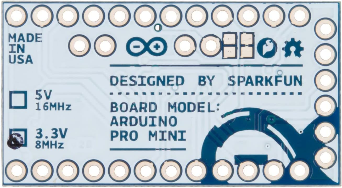
Figure 3: The underside of the Pro Mini, indicating its 3.3V and 8MHz operating characteristics.
3. Усталёўка і падключэнне
3.1 Размяшчэнне распиновокview
The Pro Mini features various pins for power, communication, and general-purpose input/output (GPIO). Understanding the pinout is crucial for proper integration into your projects.

Малюнак 4: Верх view of the Pro Mini, highlighting the various pin labels for identification.

Figure 5: Comprehensive pinout diagram detailing the functions of each pin on the SparkFun Pro Mini.
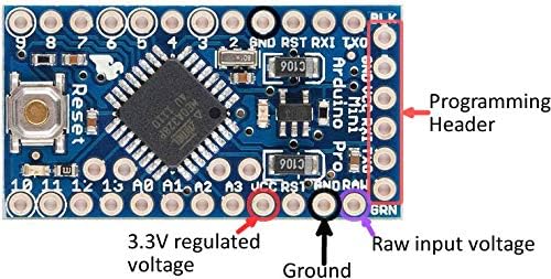
Малюнак 6: Буйны план view of the Pro Mini, labeling the programming header, 3.3V regulated voltage, ground, and raw input voltagэлектронныя шпількі.
3.2 Уключэнне харчавання платы
The Pro Mini can be powered in two primary ways:
- RAW Pin: Connect an unregulated DC voltage source between 3.4V and 12V to the RAW pin. The on-board regulator will convert this to 3.3V for the microcontroller.
- VCC Pin: If you have a pre-regulated 3.3V power supply, connect it directly to the VCC pin. Do not apply more than 3.3V to this pin.
Ensure that the power source is correctly connected to avoid damage to the board. The board includes over-current protection for the regulator.
3.3 Programming the Board
The SparkFun Pro Mini does not have an on-board USB connector. To program the board, an external FTDI Basic Breakout board (or a compatible USB-to-serial converter) is required.
- Connect the FTDI Basic Breakout board to the programming header pins on the Pro Mini. Ensure the pins (GND, VCC, RXI, TXO, RST, BLK) align correctly.
- Connect the FTDI Basic Breakout board to your computer via a USB cable.
- Адкрыйце Arduino IDE.
- Select "Arduino Pro or Pro Mini" from the "Tools > Board" menu.
- Select "ATmega328 (3.3V, 8 MHz)" as the processor.
- Choose the correct COM port for your FTDI device under "Tools > Port".
- You can now upload your sketches to the Pro Mini.

Figure 7: The SparkFun Pro Mini connected to an FTDI Basic Breakout board for programming via USB.
4. Аперацыя
4.1 Basic Sketch Upload
After successfully connecting and configuring the board in the Arduino IDE, you can upload any compatible Arduino sketch. A common first step is to upload the "Blink" example sketch to verify basic functionality.
4.2 Падключэнне перыферыйных прылад
The 3.3V operating voltage of this Pro Mini makes it ideal for direct interfacing with many modern sensors and modules that also operate at 3.3V. When connecting peripherals, always ensure voltage compatibility. If a peripheral requires 5V, a logic level shifter will be necessary to prevent damage to the Pro Mini.
- Лічбавы ўвод/вывад: Use digital pins for on/off control, reading switches, or controlling LEDs.
- Аналагавы ўваход: Pins A0-A7 can read analog sensor values.
- Паслядоўная сувязь: Use RXI/TXO pins for serial communication with other devices.
- Сувязь I2C: The board supports I2C communication, with optional pull-up resistor footprints available.

Figure 8: The Pro Mini integrated into a breadboard circuit with other electronic components, demonstrating typical usage.

Figure 9: A compact project example utilizing the SparkFun Pro Mini, powered by a small battery.
5. Тэхнічнае абслугоўванне
The SparkFun Pro Mini is a robust development board, but proper care ensures its longevity and reliable operation.
- Апрацоўка: Always handle the board by its edges to avoid touching components, especially the microcontroller, which can be sensitive to static electricity.
- захоўванне: Store the board in an anti-static bag when not in use, away from dust and moisture.
- Уборка: If necessary, gently clean the board with isopropyl alcohol and a soft brush. Ensure the board is completely dry before applying power.
- крыніца харчавання: Always verify your power supply voltage and polarity before connecting to the board. Incorrect voltage or reverse polarity can cause permanent damage.
6. Выпраўленне непаладак
- Board Not Recognized by IDE:
- Ensure your FTDI Basic Breakout board drivers are correctly installed on your computer.
- Verify that the FTDI board is properly connected to the Pro Mini's programming header.
- Check that the correct COM port is selected in the Arduino IDE.
- Confirm that "Arduino Pro or Pro Mini" is selected as the board and "ATmega328 (3.3V, 8 MHz)" as the processor.
- Sketch Upload Fails:
- Check all connections between the FTDI board and Pro Mini.
- Ensure the power supply to the Pro Mini is stable and within the specified range (3.3V to VCC or 3.4-12V to RAW).
- Sometimes, pressing the reset button on the Pro Mini just before or during the upload process can help.
- Няма харчавання/святлодыёды выключаны:
- Verify your power source is active and providing the correct voltage.
- Check the polarity of your power connections.
- If using the RAW pin, ensure the voltage is between 3.4V and 12V. If using VCC, ensure it is a regulated 3.3V.
- Нечаканая паводзіна:
- Double-check your wiring for shorts or incorrect connections.
- Ensure all connected peripherals are compatible with 3.3V logic levels. Use level shifters if necessary for 5V components.
- Review ваш код на наяўнасць лагічных памылак.
7. Тэхнічныя характарыстыкі
| Асаблівасць | Спецыфікацыя |
|---|---|
| Мікракантролер | ATmega328 |
| Аперацыйная Voltage | 3.3В |
| Уваходны кнtage (RAW) | 3.4 В - 12 В пастаяннага току |
| Тактавая частата | 8 МГц |
| Флэш-памяць | 32 KB (ATmega328) |
| SRAM | 2 KB (ATmega328) |
| ЭСППЗУ | 1 KB (ATmega328) |
| Кантакты лічбавага ўводу/вываду | 14 (6 with PWM support) |
| Кантакты аналагавага ўваходу | 8 (A0-A7) |
| Max Current per I/O Pin | 40 мА |
| Памеры | 0.7 х 1.3 цалі (18 х 33 мм) |
| Вага | 0.32 унцыі |
| Тэхналогія падлучэння | I2C, Serial (UART) |
8. Гарантыя і падтрымка
For technical support, warranty information, or further assistance with your SparkFun Pro Mini ATmega328-3.3V/8MHz Development Board, please refer to the official SparkFun Electronics webсайт або звярніцеся непасрэдна ў службу падтрымкі кліентаў.