1. Уводзіны
This manual provides detailed instructions for the installation, operation, and maintenance of the Supermicro MBD-X10SLH-F-O uATX Server Motherboard. Please read this manual thoroughly before beginning installation to ensure proper setup and to maximize the performance and longevity of your system. This motherboard is designed for server applications, supporting Intel LGA1150 processors and DDR3 memory.
2. Прадукт скончыўсяview
The Supermicro MBD-X10SLH-F-O is a high-performance uATX server motherboard featuring the Intel C226 chipset. It is engineered for reliability and efficiency in server environments.
Асноўныя характарыстыкі:
- Раз'ём працэсара: LGA1150, supporting Intel Xeon E3-1200 v3/v4 series, 4th/5th Gen Core i3, Pentium, Celeron processors.
- Памяць: 4x 204-pin DDR3-1600 SODIMM slots, supporting up to 32GB ECC/non-ECC Unbuffered memory.
- Слоты пашырэння: 1x PCI-Express 3.0 x16, 1x PCI-Express 2.0 x8, 1x PCI-Express 2.0 x4.
- захоўванне: 6x SATA3 (6Gbps) ports.
- Падключэнне: Dual Gigabit Ethernet LAN ports (2x RJ45) and 1x Dedicated IPMI LAN port (RJ45).
- Парты USB: 4x USB 3.0 ports, 6x USB 2.0 ports.
- Відэа выхад: 1x VGA port.
- Формаў-фактар: uATX (9.6" x 9.6").
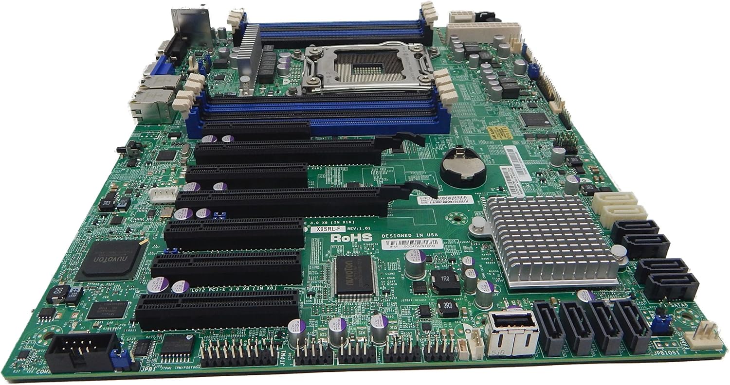
Малюнак 2.1: Зверху ўніз view of the Supermicro MBD-X10SLH-F-O motherboard, showing the CPU socket, RAM slots, and various expansion slots.

Малюнак 2.2: Вуглавы view of the motherboard, highlighting the LGA1150 CPU socket and the four DDR3 SODIMM memory slots.

Малюнак 2.3: Тыл view of the Supermicro MBD-X10SLH-F-O motherboard, displaying the I/O panel with USB, VGA, LAN, and IPMI ports.

Малюнак 2.4: Буйны план view of the motherboard, showing the six SATA3 ports and other onboard connectors.
3. Тэхнічныя характарыстыкі
| Асаблівасць | Спецыфікацыя |
|---|---|
| Марка | Супермікра |
| Назва мадэлі | MBD-X10SLH-F-O |
| Гняздо працэсара | LGA 1150 |
| Тып чыпсэта | Intel C226 |
| Сумяшчальныя працэсары | Intel Core i3-4xxx, i5-4xxx, i7-4xxx, i3-5xxx, i5-5xxx, i7-5xxx, Intel Xeon E3-1200 v3/v4 series |
| Тэхналогія аператыўнай памяці | DDR3 |
| Хуткасць памяці | 1600 МГц |
| Максімальная падтрымоўваная аператыўная памяць | 32 ГБ |
| Колькасць партоў USB 2.0 | 6 |
| Колькасць партоў USB 3.0 | 4 |
| Парты SATA | 6x SATA3 (6Gbps) |
| Слоты пашырэння | 1x PCIe 3.0 x16, 1x PCIe 2.0 x8, 1x PCIe 2.0 x4 |
| Формаў-фактар | uATX |
| Памеры (ДхШхВ) | 14 х 11 х 3.5 цалі |
| Вага прадмета | 3.52 унцыі |
4. Настройка
Before beginning installation, ensure your system is powered off and disconnected from the power source. Always handle the motherboard by its edges to avoid static discharge.
4.1. Усталёўка працэсара
- Gently lift the CPU socket lever.
- Сумясціце працэсар з сокетам, пераканаўшыся, што залаты трохкутнік на працэсары супадае з трохкутнікам на сокеце.
- Carefully place the CPU into the socket without forcing it.
- Lower the socket lever and secure it.
- Нанесці цеплавую пасту і ўсталяваць кулер працэсара ў адпаведнасці з інструкцыямі вытворцы.
4.2. Усталёўка памяці
- Адкрыйце зашчапкі з абодвух канцоў слота DIMM.
- Align the memory module's notch with the key in the DIMM slot.
- Моцна націсніце на абодва канцы модуля памяці, пакуль зашчапкі не зафіксуюцца.
4.3. Усталёўка платы пашырэння
- Remove the corresponding slot cover from your chassis.
- Сумясціце карту пашырэння з патрэбным слотам PCIe.
- Press down firmly until the card is fully seated.
- Замацуеце карту шрубай або заціскам.
4.4. Падключэнне прылады захоўвання дадзеных
- Падключыце адзін канец кабеля перадачы дадзеных SATA да порта SATA на матчынай плаце.
- Connect the other end of the SATA data cable to your storage device (HDD/SSD).
- Падключыце кабель харчавання SATA ад блока харчавання да прылады захоўвання дадзеных.
4.5. Падключэння харчавання
- Падключыце 24-кантактны раз'ём асноўнага харчавання ATX ад блока харчавання да матчынай платы.
- Падключыце 8-кантактны (або 4-кантактны) раз'ём харчавання працэсара ATX 12V да матчынай платы.
4.6. Падключэнні пярэдняй панэлі
Connect the front panel headers (Power LED, HDD LED, Power Switch, Reset Switch, USB, Audio) to the corresponding pins on the motherboard. Refer to the motherboard's silkscreen labels for correct pin orientation.
5. Інструкцыя па эксплуатацыі
5.1. Пачатковая загрузка
- After all components are installed and connected, connect the power cord to your power supply and turn on the power switch.
- Націсніце кнопку харчавання на корпусе.
- The system should power on, and you should see a display on your monitor.
5.2. Доступ да BIOS/UEFI
To enter the BIOS/UEFI setup utility, press the designated key (commonly DEL or F2) during the initial boot sequence. The exact key may vary; observe the on-screen prompts.
5.3. IPMI Remote Management
This motherboard features a dedicated IPMI LAN port for remote management. To access the IPMI interface, connect the IPMI LAN port to your network. Obtain the IP address assigned to the IPMI interface (either from BIOS or a network scan) and access it via a web browser from another computer on the same network. Java may be required for remote console functionality.
6. Тэхнічнае абслугоўванне
Рэгулярнае тэхнічнае абслугоўванне дапамагае забяспечыць стабільнасць і даўгавечнасць вашай матчынай платы і сістэмы.
- Выдаленне пылу: Перыядычна чысціце матчыну плату і кампаненты ад пылу сціснутым паветрам. Перад чысткай пераканайцеся, што сістэма выключана і адключана ад сеткі.
- Кабельнае кіраванне: Пераканайцеся, што ўсе кабелі акуратна пракладзены і замацаваны, каб прадухіліць перашкоды для паветранага патоку і выпадковае адключэнне.
- Абнаўленні BIOS/прашыўкі: Праверце Supermicro website for the latest BIOS and IPMI firmware updates. Follow the provided instructions carefully. Note that IPMI BIOS upgrades may require a separate license. Always update BIOS before IPMI firmware.
- Праверка кампанентаў: Occasionally inspect all connections (power, data, expansion cards) to ensure they are securely seated.
7. Выпраўленне непаладак
У гэтым раздзеле разглядаюцца распаўсюджаныя праблемы, з якімі вы можаце сутыкнуцца.
7.1. System Fails to Boot
- Праверце злучэнне харчавання: Ensure the 24-pin ATX and 8-pin CPU power connectors are securely attached.
- Пераўсталюйце кампаненты: Remove and re-install the CPU, memory modules, and any expansion cards to ensure they are properly seated.
- Ачысціць CMOS: Refer to your motherboard's detailed manual for instructions on how to clear the CMOS, which can resolve boot issues caused by incorrect BIOS settings.
- Minimum Configuration: Try booting with only essential components (CPU, one RAM stick, power supply, and display) to isolate the problem.
7.2. Fan Speed Issues
Some low RPM, high-efficiency fans may not be accurately detected by the motherboard's fan controller, leading to erratic fan speed behavior (e.g., fans spinning up to max RPM). This is often due to the controller expecting server-grade fans with higher RPM ranges.
- Налады BIOS: Check BIOS settings for fan control options. Adjust fan curves or modes if available.
- 3-Pin vs. 4-Pin Fans: If using 4-pin PWM fans that exhibit this behavior, consider using 3-pin adapters if available with your fans. This can sometimes provide a more stable, albeit less precise, fan control.
- IPMI Fan Control: While IPMI offers fan control, it may have limitations for low RPM fans.
7.3. SATA Port Obstruction
When installing a full-size graphics processing unit (GPU), some SATA ports may become physically blocked or difficult to access.
- Плануйце наперад: Connect SATA cables to the necessary ports before installing large expansion cards.
- Angled SATA Cables: Use SATA cables with angled connectors if straight connectors are obstructed.
- Alternative Ports: Utilize any unblocked SATA ports first.
8. Інфармацыя аб гарантыі і падтрымцы
For detailed warranty information, including terms, conditions, and duration, please refer to the official Supermicro website or the warranty card included with your product. For technical support, driver downloads, and additional documentation, visit the Supermicro support portal.
Афіцыйны прадстаўнік Supermicro Webсайт: www.supermicro.com