1. Уводзіны
This manual provides essential information for the safe and effective installation, operation, and maintenance of the Danfoss MCI 15 Motor Controller, model 037N0039. Please read this manual thoroughly before attempting to install or operate the device. Retain this manual for future reference.
2. Інфармацыя па бяспецы
Заўсёды выконвайце наступныя меры бяспекі, каб пазбегнуць траўмаў або пашкоджання абсталявання:
- Усталёўку і абслугоўванне павінны выконваць толькі кваліфікаваныя спецыялісты.
- Перад тым, як праводзіць якія-небудзь мантажы электраправодкі або тэхнічнае абслугоўванне, пераканайцеся, што электрасілкаванне адключана.
- Verify all connections are secure and correctly wired according to the provided diagrams.
- Абараняйце прыладу ад вільгаці, пылу і экстрэмальных тэмператур.
- Do not operate the controller if it appears damaged.
3. Прадукт скончыўсяview
The Danfoss MCI 15 Motor Controller is designed for controlling motor speed and soft starting applications. It features robust construction with an integrated heat sink for efficient thermal management.


4. Тэхнічныя характарыстыкі
Key technical specifications for the Danfoss MCI 15 Motor Controller:
| Параметр | Каштоўнасць |
|---|---|
| Нумар мадэлі | MCI 15 (037N0039) |
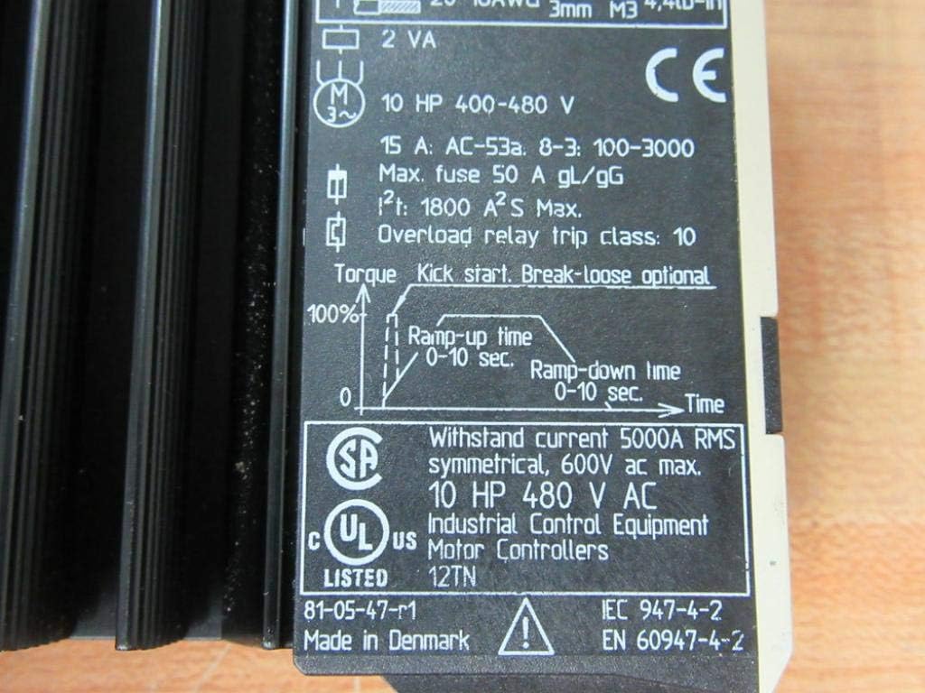
| Намінальны ток (Ie) | Max 15 A AC 53a |
| Кантроль Voltagе (Uc) | 24-480 В пераменнага/пастаяннага току |
| Аперацыйная Voltagе (Ue) | 380-480 В 50/60 Гц |
| Ізаляцыя Voltage (Ui) | 660В |
| Impulse Stand Voltagе (Uimp) | 4 кВ |
| Памеры прадукту | 5 х 5 х 2 цалі |
| Вага прадмета | 1.35 фунта |
| Матэрыял | Copper (heat sink) |
| Максімальны засцерагальнік | 50 А гЛ/гГ |
| Overload Relay Trip Class | 10 |
| HP Rating (400-480V) | 10 HP |

5. Настройка і ўстаноўка
5.1 Мантаж
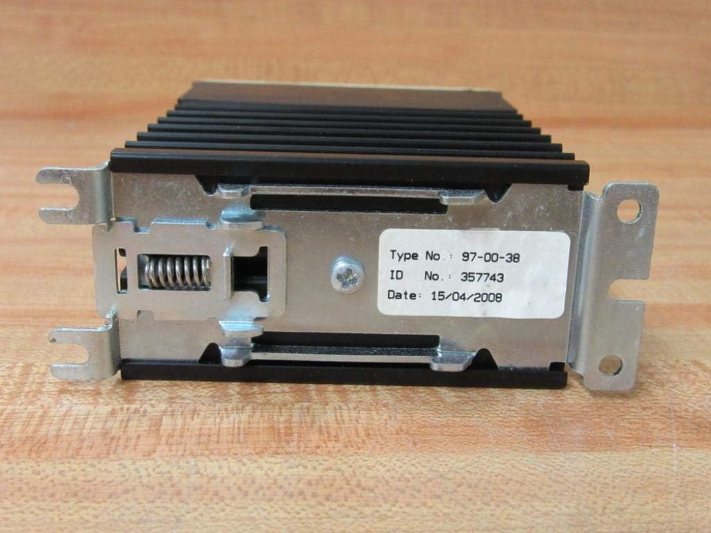
The Danfoss MCI 15 Motor Controller is designed for panel mounting. Ensure adequate ventilation around the heat sink to prevent overheating. Use appropriate fasteners through the mounting brackets shown in Figure 3.4.
5.2 Электраправодка
Refer to the wiring diagram on the device label (Figure 4.1) for correct connections. Ensure all wiring adheres to local electrical codes and safety standards.
- Power Input (L1, L2, L3): Connect the three-phase power supply to terminals 1/L1, 3/L2, and 5/L3.
- Motor Output (T1, T2, T3): Connect the motor leads to terminals 2/T1, 4/T2, and 6/T3.
- Control Input (A1, A2): Падключыце кантрольны абtage to terminals A1 and A2.
- Use recommended wire sizes (e.g., 0.75-6mm² or 18-10AWG for power, 0.5-1.5mm² or 20-16AWG for control) and tighten terminals to the specified torque (e.g., 0.5Nm or 4.4lb-in for M3 screws).
5.3 Пачатковыя налады
Before initial operation, adjust the potentiometers on the front panel (Figure 3.2) to desired settings:
- Ramp Час працы: Adjust the 'up' potentiometer to set the motor acceleration time (0-10 seconds).
- Ramp Down Time: Adjust the 'down' potentiometer to set the motor deceleration time (0-10 seconds).
- Kick Start: Adjust this potentiometer to provide an initial torque boost for starting loads.
- Initial Torque: Adjust this potentiometer to set the initial torque level during startup.
6. Інструкцыя па эксплуатацыі
Once installed and configured, the Danfoss MCI 15 Motor Controller operates by applying a controlled voltagэamp to the motor, providing a soft start and stop. The motor will accelerate to full speed over the set ramp-up time and decelerate over the set ramp- час прастою.
- Ужыць кантроль абtage to terminals A1 and A2 to initiate motor operation.
- Remove control voltage to initiate motor stop (soft stop).
- Monitor motor performance and adjust ramp times and torque settings as needed for optimal operation.
7. Тэхнічнае абслугоўванне
Regular maintenance ensures the longevity and reliable operation of the motor controller.
- Уборка: Periodically clean the exterior of the controller, especially the heat sink fins, to ensure proper heat dissipation. Use a dry, soft cloth. Do not use solvents or abrasive cleaners.
- агляд: Regularly inspect wiring connections for tightness and signs of wear or damage. Check for any discoloration or unusual odors, which may indicate overheating.
- Асяроддзе: Забяспечце, каб тэмпература і вільготнасць у рабочым асяроддзі знаходзіліся ў межах зададзеных дыяпазонаў.
8. Выпраўленне непаладак
If the motor controller does not operate as expected, consider the following basic troubleshooting steps:
- No Motor Start: Verify power supply to the controller and motor. Check control signal to A1/A2. Ensure all wiring is correct and secure.
- Перагрэў рухавіка: Check for proper ventilation around the heat sink. Ensure the motor is not overloaded. Verify motor parameters are correctly set.
- Incorrect Ramp Час: Re-adjust the 'up' and 'down' potentiometers on the front panel.
- Unexpected Stops: Check for power fluctuations or intermittent control signals. Inspect for any fault indicators if available on the device or system.
For complex issues, contact Danfoss technical support.
9. Гарантыя і падтрымка
Каб атрымаць інфармацыю аб гарантыі на прадукцыю, тэхнічнай падтрымцы або абслугоўванні, звярніцеся да афіцыйнага сайта Danfoss. website or contact your local Danfoss representative. Ensure you have the model number (MCI 15) and serial number (if applicable, visible on the rear label, Figure 7.1) available when contacting support.