
1. Уводзіны
This manual provides detailed instructions for the installation, operation, and maintenance of the QIACHIP Mini Wireless Remote Control Switch. This device is designed to provide wireless control for various DC applications, including LED lights, car batteries, and door locks, operating within a voltage дыяпазон пастаяннага току ад 6 В да 60 В.

Figure 1: QIACHIP Mini Wireless Remote Control Switch (1 Receiver + 1 Transmitter)
2. Прадукт скончыўсяview
Асноўныя характарыстыкі:
- Шырокі Voltagе дыяпазон: Увод абtage DC 5V-60V, supporting various DC applications.
- Высокая магутнасць току: Maximum relay contact current of 20 Amps.
- ВЧ частата: Operates on 433 MHz for reliable wireless communication.
- Extended Transmission Distance: Approximately 50-100m in open spaces. The antenna can be extended for improved reception.
- Некалькі рэжымаў працы: Supports Momentary, Toggle, Latched, and Delay modes.
- Сумяшчальнасць з дыстанцыйным кіраваннем: Supports EV1527 learning code remote controllers, allowing pairing with up to 20 remotes.
- Кампактны дызайн: PCB size of 47 x 26 x 18 mm (L, W, H).
- Універсальныя прымянення: Suitable for car battery power control, garage doors, electronic doors, appliances, motorcycle alarms, car sunroofs, and heating systems.

Figure 2: Product application examples for lighting control.

Figure 3: Enhanced features of the remote switch, including an exposed antenna for better reception and a wider voltagе дыяпазон.
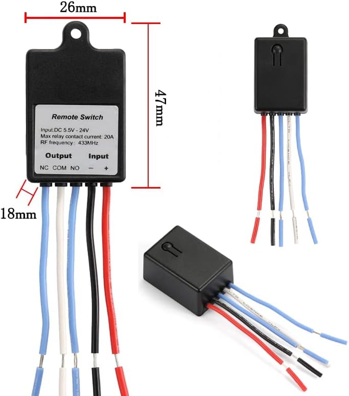
Figure 4: Physical dimensions of the remote control switch.

Figure 5: Internal components and terminal labels of the remote switch.
3. Тэхнічныя характарыстыкі
| Спецыфікацыя | Каштоўнасць |
|---|---|
| Рэжым працы | УКЛ ВЫКЛ |
| Бягучы рэйтынг | 20 Amps |
| Аперацыйная Voltage | Пастаянны ток 5-60 В |
| Тып кантакту | Normally Open (NO), Normally Closed (NC), Common (COM) |
| Тып раздыма | Бесправадная сувязь |
| Тэрмінал | Прыпой |
| Памеры прадмета (Д х Ш х У) | 1.85 х 1.02 х 0.71 цалі (47 х 26 х 18 мм) |
| Тып схемы | 1-баковы |
| Кантактны матэрыял | Пластыкавыя |
| Міжнародны рэйтынг абароны | IP54 |
| Колькасць пазіцый | 2 |
| Метад кантролю | Дыстанцыйнае |
| Пратакол злучэння | 433 МГц |
| Ватtage | 480 ват |
| Вага прадмета | 1.76 унцыі |
| Батарэі (перадатчык) | Патрабуецца 1 батарэя CR2032 (у камплекце) |
4. Мантаж і праводка
The QIACHIP remote control switch features three output terminals: NC (нармальна закрыты), COM (Агульны), і НЕ (нармальна адкрыты). These terminals function like a Single-Pole Double-Throw (SPDT) switch. The input terminals are labeled + і - for DC power connection.
Wiring Principles:
- COM: This is the common terminal where the power source or load is typically connected.
- NC: Normally Closed. This terminal is connected to COM by default when the relay is inactive.
- НЕ: Normally Open. This terminal is disconnected from COM by default when the relay is inactive. It connects to COM when the relay is activated.
- Input Power (+ and -): Connect your DC power supply (5V-60V) to these terminals to power the receiver module.
Typical Wiring Diagrams:

Figure 6: Wiring for a DC load (e.g., LED light). The load is connected to NO and COM, and the receiver is powered by the DC source.

Figure 7: Wiring for an access control or door lock system. The lock is connected to NO and COM, and the receiver is powered by the DC source.

Figure 8: Wiring for an external power supply load. The remote switch controls the load's circuit via NO and COM, while the load has its own power source.
Важна: Заўсёды пераканайцеся, што крыніца харчаванняtage matches the requirements of your load and the remote switch. Incorrect wiring can damage the device or connected components.
5. Operating Modes and Pairing Instructions
The QIACHIP remote control switch supports four operating modes: Momentary, Toggle, Latched, and Delay. Each mode offers different control behaviors. To change modes, you must first perform a reset. After the reset, all previously paired remote controls are temporarily deactivated.
Video: Wiring and Pairing Demonstration
Video 1: This video demonstrates the wiring process and how to pair the remote control switch in different operating modes (Momentary, Toggle, Latched, and Delay Off).
5.1. Кароткачасовы рэжым
In Momentary mode, the output is active only while the remote button is pressed. Releasing the button deactivates the output.
- Спалучэнне: Press the learning button on the receiver адзін раз. The indicator light will turn on. Then, press any button on your remote control. The indicator light will flash and turn off, indicating successful pairing.

Figure 9: Momentary Mode operation.
5.2. Пераключыце рэжым
In Toggle mode, pressing the remote button once activates the output, and pressing it again deactivates the output.
- Спалучэнне: Press the learning button on the receiver двойчы. The indicator light will turn on. Then, press any button on your remote control. The indicator light will flash and turn off, indicating successful pairing.

Figure 10: Toggle Mode operation.
5.3. Заблакаваны рэжым
In Latched mode, one remote button activates the output, and another remote button deactivates it. This mode requires a multi-button remote.
- Спалучэнне: Press the learning button on the receiver тры разы. The indicator light will turn on. Then, press the first button (e.g., 'A') on your remote, followed by the second button (e.g., 'B'). The indicator light will flash and turn off, indicating successful pairing.

Figure 11: Latched Mode operation.
5.4. Delay Off Mode
In Delay Off mode, the output activates when the remote button is pressed and remains active for a set duration (e.g., 5, 10, 15, or 20 seconds) before automatically deactivating.
- Pairing for 5-second delay: Press the learning button on the receiver чатыры разы. The indicator light will turn on. Then, press any button on your remote control. The indicator light will flash and turn off, indicating successful pairing.
- Pairing for 10-second delay: Press the learning button on the receiver пяць разоў.
- Pairing for 15-second delay: Press the learning button on the receiver шэсць разоў.
- Pairing for 20-second delay: Press the learning button on the receiver сем разоў.

Figure 12: Delay Off Mode operation.
5.5. Resetting All Paired Remotes
To clear all previously paired remote controls and reset the receiver to its default state, follow these steps:
- Press the learning button on the receiver eight times. The indicator light will flash rapidly and then turn off. This indicates that all stored remote control data has been erased.
6. Тэхнічнае абслугоўванне
The QIACHIP Mini Wireless Remote Control Switch is designed for durability and requires minimal maintenance. Keep the device clean and free from dust and moisture. Ensure all wiring connections are secure to prevent intermittent operation. Replace the CR2032 battery in the transmitter when its range decreases or it stops responding.
7. Выпраўленне непаладак
- Device not responding to remote:
- Check if the remote control battery is depleted. Replace if necessary.
- Ensure the receiver is powered correctly (DC 5V-60V).
- Verify that the remote is paired correctly to the receiver in the desired mode. If unsure, perform a reset and re-pair.
- Check for strong RF interference in the environment.
- Reduced remote control range:
- Заменіце батарэю пульта дыстанцыйнага кіравання.
- Ensure the receiver's antenna is not obstructed and is extended if possible.
- Minimize physical obstructions (walls, metal objects) between the remote and receiver.
- Output not activating/deactivating correctly:
- Verify wiring connections to NC, COM, and NO terminals are correct for your application.
- Ensure the load's power requirements do not exceed the relay's maximum contact current (20A) or wattage (480 Вт).
- Confirm the operating mode is set as intended (Momentary, Toggle, Latched, Delay).
- Indicator light not functioning:
- Check the power supply to the receiver.
- If the device is otherwise functional, the indicator light may be faulty, but this does not affect core operation.
8. Гарантыя і падтрымка
For warranty information or technical support, please refer to the product packaging or contact QIACHIP customer service through the retailer where the product was purchased. Keep your purchase receipt for warranty claims.